Currently available for freelance and full-time roles in the experiential media space!
Jason Webb

Tube Gardens for Artist in Residence show
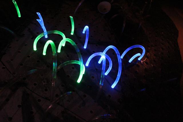
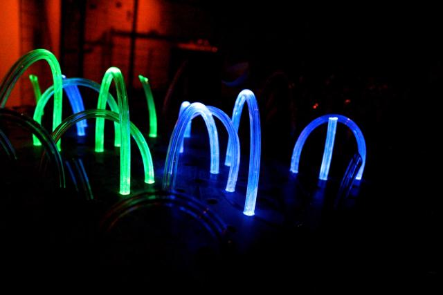
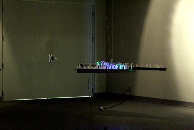
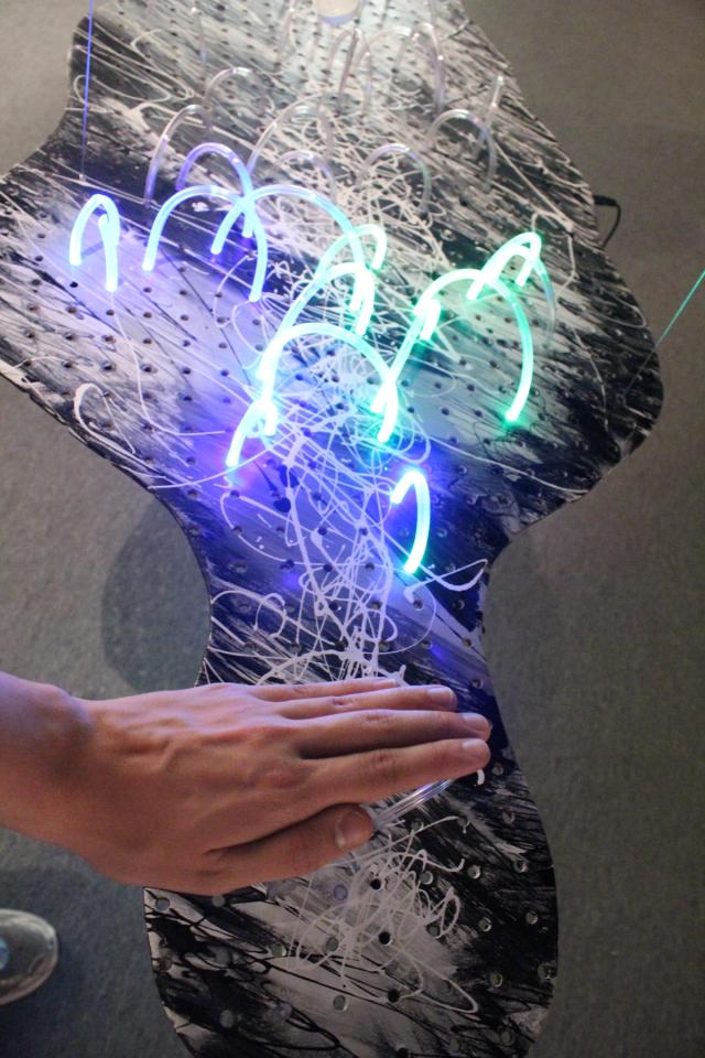
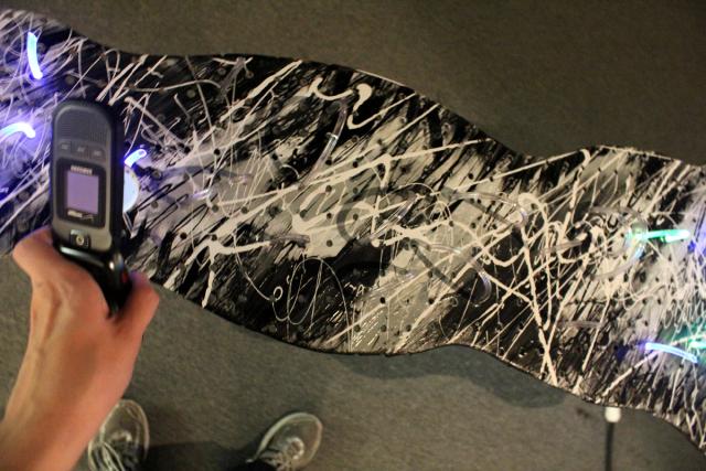
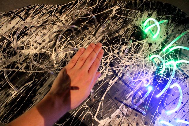
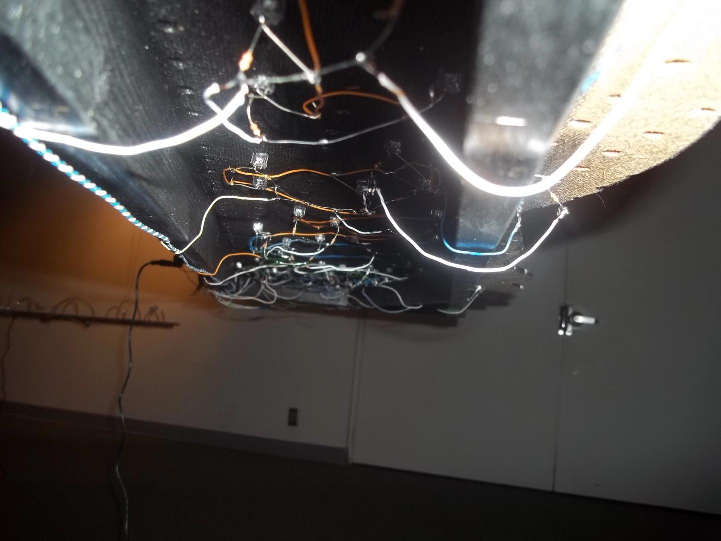
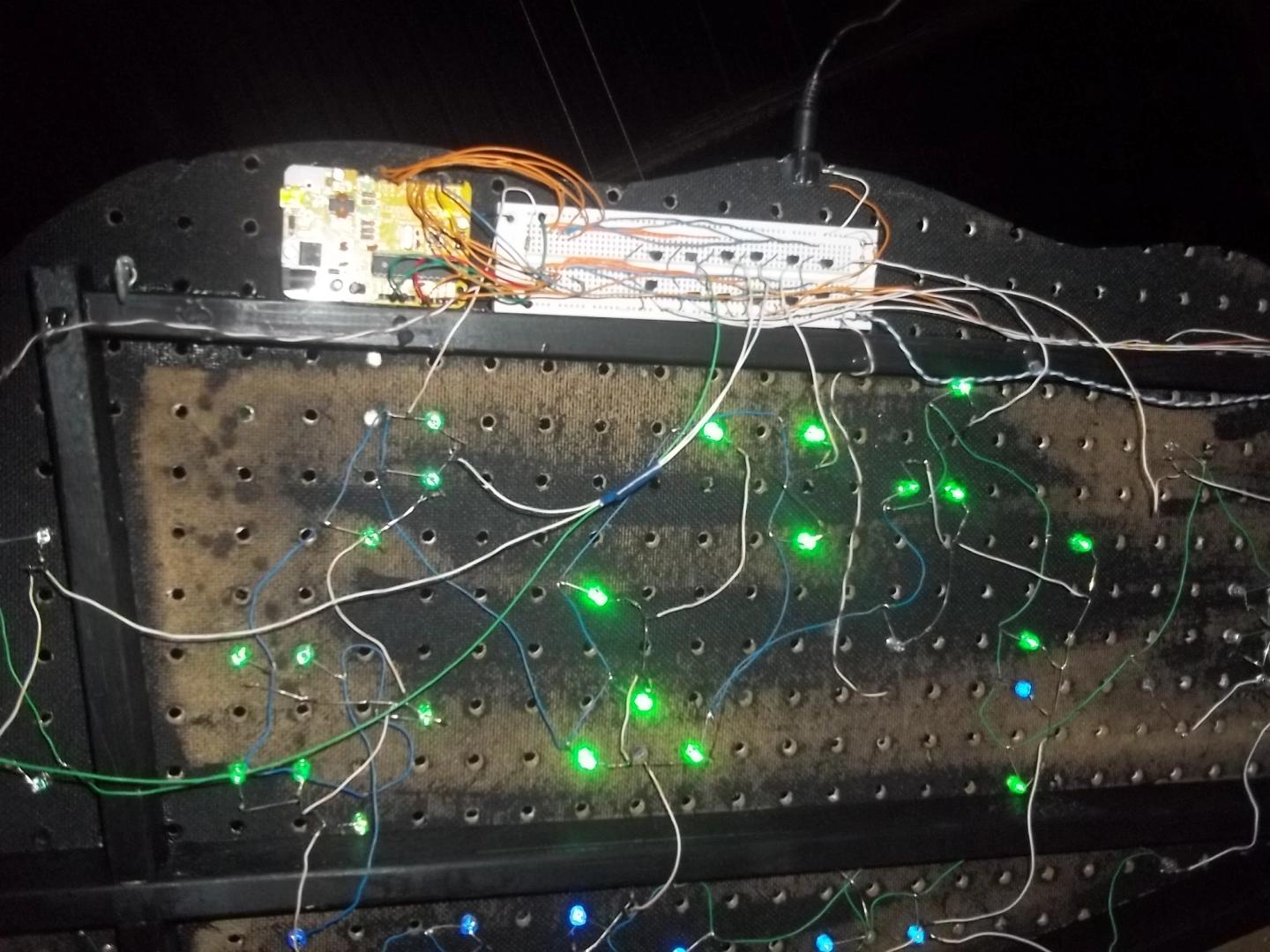
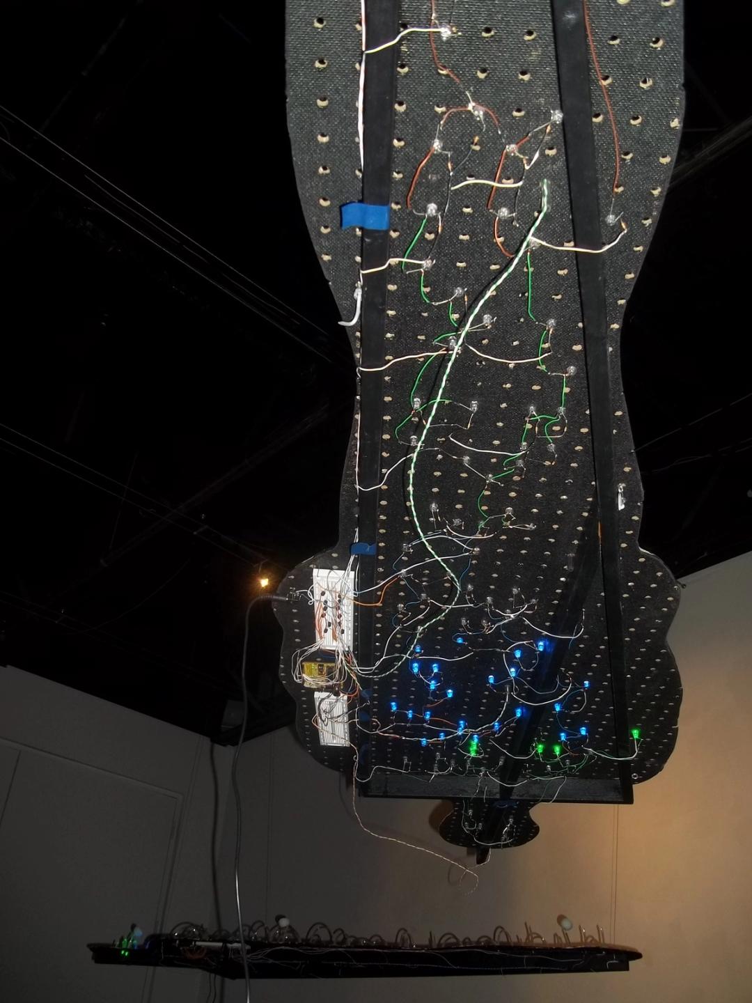
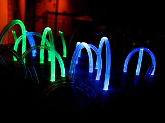
October 2011

As part of the Artist in Residence show, I collaborated with Mark Hartman, professor of Visual Communcations and Design at the University of Nebraska at Kearney, to create a series of life-sized human forms outfitted with medical tubing, high-brightness LEDs and CdS photocells. The project began as a simple undertaking to create an interactive, aesthetically interesting field of light, but it took on deeper meaning over the build process.

The project began with the idea to make use of a batch of medical tubing I had laying around my workbench by shining high-brightness LEDs into their ends and letting them light up and glow thanks to a neat optics effect called Total Internal Reflection (TIR). Thanks to this beautiful phenomenon, a good amount of light emitted by the LED travels through the length of the tubing, just like how light travels through fiber optic lines. When the angle of the light rays bouncing around within the tubing exceeds a certain angle (the “critical angle”), the light escapes, which is how you see it. You can actually exploit this cool trick to create light-based multi-touch surfaces, like the prototypes I built as an undergrad! When I find some time, I’d like to hook up an LED in one of the tubing, and a CdS photocell in the other, and see if I can bend the tubing to vary the light falling on the photocell (maybe even patch it into a synth and make some music).

Although I used medical tubing, you can actually find very similar tubing in your local hardware store’s plumbing section labelled as “PEX tubing”. Bring an LED with you, and you should be able to find a size of tubing that the LED fits into snugly, without the need for any glue! Luckily, my tubing fit perfectly into the holes of some spare pegboard, so the LEDs could be mounted to the wooden form with no extra parts!

Once these forms had been cut by Mark, and most of the LEDs and medical tubing had been attached, the next step was to determine how the LEDs should behave, which in turn would dictate how the LEDs should be wired up and controlled.

Parts list

Wiring up the LEDs

Regardless of how I would want the LEDs to light up, they would all need to have a common ground. This meant that all of the anodes (short wires) of all of the LEDs needed to be wired together. Since there were approximately 120+ LEDs for the two large tube gardens, and about 30+ LEDs for the small tube garden, this amounted to a pretty good amount of soldering!

Once all of the anodes had been wired up, the LEDs had to be connected to a controller so that they can be turned on and off. Wiring up the LEDs so that each LED was individually addressable was a possibility, but I didn’t want to spend too much time on this piece, so I opted to wire up larger groups of LEDs to ‘share’ control signals. I divided the tube gardens into 11 equal-sized groups (spatially, not by number of LEDs) and soldered each cathode of all of the LEDs in each group to each other, then ran one wire from each group to an Arduino for control.

In case you’re wondering: yes, this is a lot of soldering. In fact, each Tube Garden done this way requires nearly 400 solder joints!

Since the ATMEGA328 found on Arduino boards can only output a maximum of 40mA per pin, and each LED consumes 20mA, it would not be possible to power groups of more than 2-3 LEDs using the Arduino directly. Instead, I put a bunch of 2n2222 transistors on breadboard that enable the Arduino to apply power from a more powerful (5VDC@1A) power supply to the groups of LEDs.

Making it interactive

Just wiring up the LEDs to flash on and off wasn’t quite enough for me, so I got a hold of a few CdS photocells from SparkFun and connected them to the Arduino analog inputs through voltage dividers using 10k resistors.

To diffuse the light reaching the CdS photocells (and to just make them look more interesting), I cut some ping pong balls in half and punched a hole in each halve. The CdS photocells were then placed inside the ping pong ball halve and secured by bending their leads a little bit.

Using the voltage dividers, a value indicating the analog voltage can be read by the Arduino and used in a sketch. Since photocells vary their resistance based on the amount of light falling on it, they can sense changes such as the photocell being covered up (less light / more resistance), or a light being shone onto it (more light / less resistance). The Arduino sketch does this by first recording the baselines values of each CdS photocell as soon as power is applied. All future readings are then compared with this baseline value, which means the Arduino can easily detect variances in the photocell resistances.

If a CdS photocell is covered up, the Arduino sketch animates the LEDs to imply motion away from the person. Similarly, when extra light is applied to a CdS photocell, the Arduino sketch animates the lights moving toward the photocell, then blinks the final group of LEDs a couple of times to greet the visitor.

Easter egg: When light is applied to a photocell and the LEDs are activated to rush towards that photocell, the final LED group actually flashes out the word “hi” in Morse Code (…. ..). In effect, the Tube Garden is trying to communicate with it’s visitors!