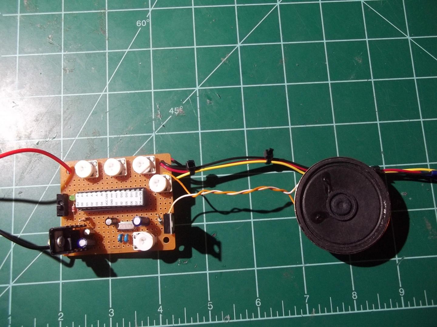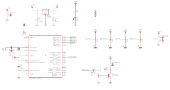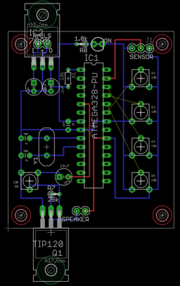
DIY synthesizer boards using ATMega328s and Auduino
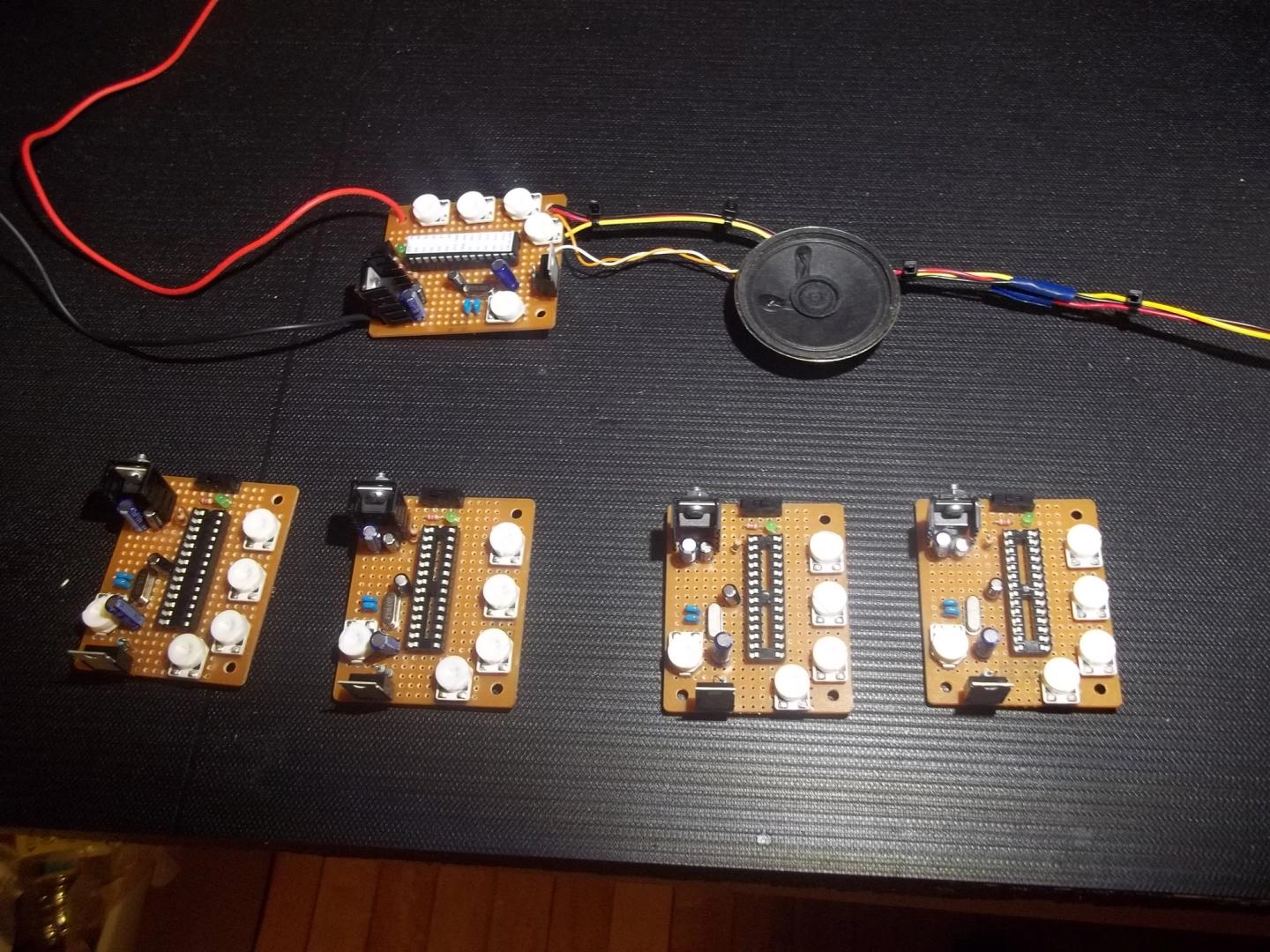
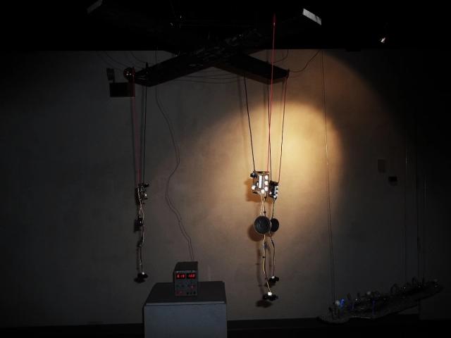
- Set of 5 custom synths
- Custom firmware that sonifies real-time distance sensor data using Auduino running on ATMega328 chips.
- The sensor data changes as visitors walk by, and because they swing a little in the air.
- Auduino quantizes the sensor data to notes on the pentatonic scale. Each synth is tuned to a different range.
- Powered by 12V light rails from which they hang
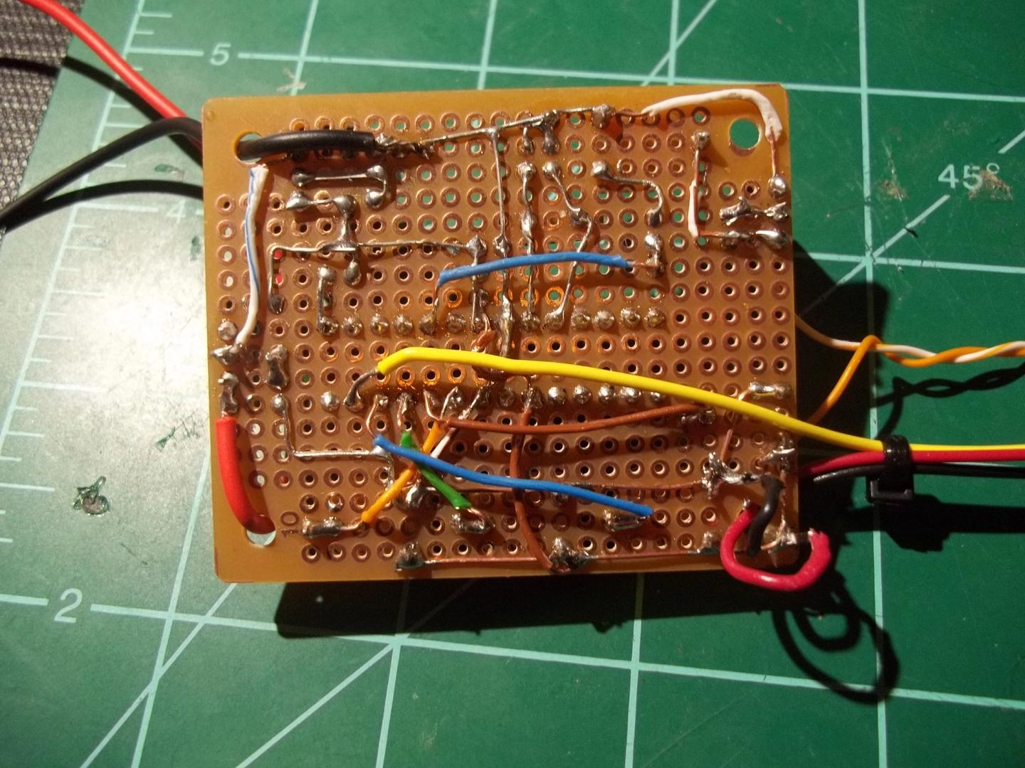
- Built on perfboard based on PCB layout in Eagle
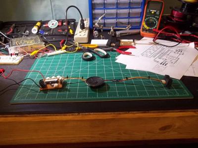
Build log