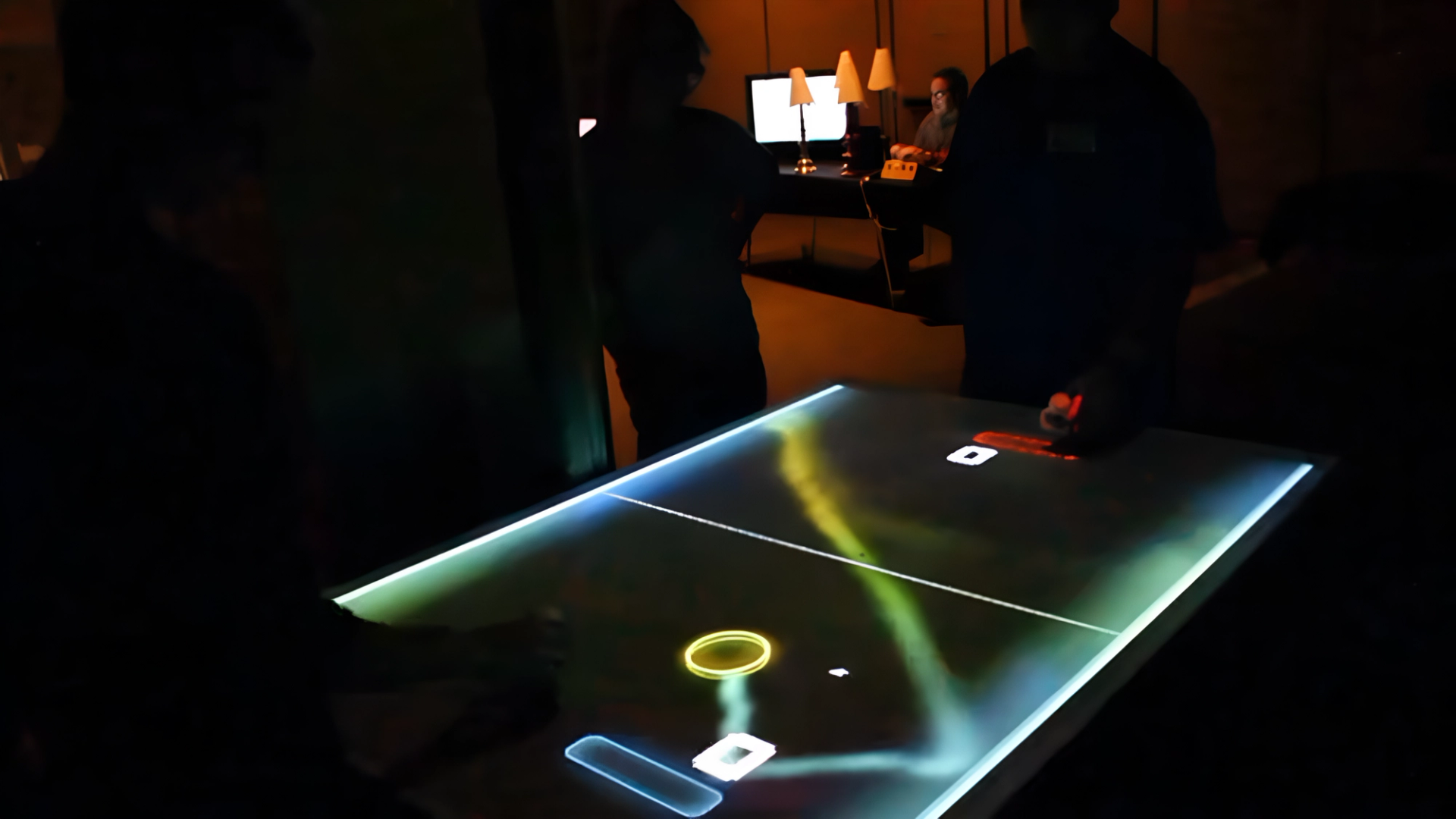
Tabletop augmented reality Pong game
The classic game of Pong re-imagined as an interactive media installation where players move their paddles using only their hands. This project was shown at the 2011 Interactive and Generative Art Exhibition, where it was an instant crowd favorite.
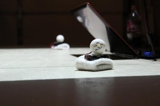
Players wear wristbands with battery-powered IR LEDs attached, which are tracked in real-time by a custom openFrameworks app using a modified PS3Eye camera. The position of the IR LEDs is mapped from the camera's coordinate space to the game's after a manual calibration process, while the game is projected onto the tabletop surface from above.
This project was built in collaboration with fellow technologist Jeff Sylvester, who built the physical frame and mounting hardware, and helped with the software calibration system.